
If you’ve ever spent time around industrial machinery—whether it’s a conveyor line at a warehouse, a motor driving a pump, or a gearbox in a manufacturing plant—you know how important it is that every component stays exactly where it’s supposed to. One tiny part that makes that happen? A shaft locking assembly. But if you’re like a lot of engineers or maintenance managers I talk to, you might’ve wondered: “Just how fast can this thing actually go?” Because when your machine is humming at high speeds, there’s no room for error—if your locking assembly fails, you’re looking at downtime, damaged parts, and possibly even safety issues. As a supplier who’s worked with hundreds of teams to pick the right locking solutions, I’m here to break down the maximum speed a shaft locking assembly can handle, what factors affect that number, and how to make sure you’re not pushing your assembly too hard.
First, let’s get one thing straight: There’s no one-size-fits-all answer to “max speed.” A lot of people think it’s just a number printed on a spec sheet, but that’s only part of it. The speed a locking assembly can handle depends on three big, interlinked factors: the type of assembly, how it’s installed, and the conditions it’s operating in. Let’s start with the most common types of locking assemblies because that’s where most folks go wrong when picking the wrong one for their speed needs.
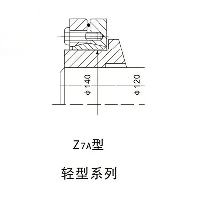
If you’re dealing with everyday applications—small to medium loads, moderate speeds—you’ll likely reach for a Shaft Locking Assembly first. These are the workhorses of the industry, designed to clamp onto a shaft and hub without keys, splines, or set screws, so they transfer torque cleanly. But their max speed? Typically, standard units top out around 10,000 RPM for small shafts (like 20mm to 50mm) and maybe 5,000 RPM for larger shafts (100mm and up). Wait, why is it lower for bigger shafts? Think about it: A larger shaft has more surface area moving faster at its outer edge, so the centrifugal force pulling the hub and locking assembly apart is stronger. That force puts stress on the locking elements—usually wedges, springs, or pressure plates—and if it’s too high, the assembly can slip or even come loose.
But not all Standard Shaft Locking Assembly units are created equal. Some manufacturers add extra spring tension or use higher-grade steel (like 4140 alloy) to handle a bit more speed. We’ve seen some standard units hit 12,000 RPM for small shafts, but that’s the upper limit for that category. If your machine is running faster than that, a standard assembly might not cut it—especially if the load is heavy. That’s where Heavy Duty Locking Assembly comes in. These are built for tough jobs: heavy loads, high speeds, and extreme environments. They use thicker steel bodies, larger clamping surfaces, and sometimes even bolted tension instead of spring tension to hold things tight. We’ve had customers use these at up to 18,000 RPM for medium shafts (60mm to 100mm) and even 15,000 RPM for 150mm shafts. How do they do it? The heavier clamping force counteracts the stronger centrifugal force at high speeds, so the hub stays locked to the shaft instead of slipping.
Wait, there’s another type that’s often overlooked: Shaft Shrink Disc Assembly. A lot of people confuse these with locking assemblies, but they’re a close cousin. Instead of mechanical clamping, shrink discs use hydraulic pressure to expand the disc, pressing it tight against the shaft and hub wall. That creates a uniform, high clamping force that’s perfect for super high speeds. We’ve seen shrink disc assemblies handle up to 25,000 RPM for small shafts, and even 18,000 RPM for large shafts. The downside? They’re a bit more expensive, and installation requires a hydraulic pump, so they’re not for every application. But if you’re running a high-speed machine like a centrifugal pump or a high-performance conveyor, they’re a solid pick.
Now, what if you’re dealing with a lightweight application? Maybe a small motor on a packaging machine or a conveyor for light goods. Then a Lightweight Shaft Locking Assembly is your go-to. These are made with thinner aluminum or composite materials to cut down on weight, which reduces centrifugal force in the first place. That means they can handle up to 14,000 RPM for small shafts—faster than standard assemblies—because their lower mass minimizes stress. The trick here is not to push them past that: if you run a lightweight assembly at 16,000 RPM, the extra centrifugal force on the light material can cause it to flex, and that flex leads to misalignment, which then causes vibration and eventually failure.


Okay, so now you know the rough speed ranges for each type, but here’s the thing: those numbers are theoretical. Real-world conditions will change everything. Let’s talk about the factors that can make your max speed higher or lower than the spec sheet says.
First, installation. I can’t tell you how many times I’ve seen a locking assembly fail not because it’s too slow, but because it was installed wrong. If you don’t tighten the clamping bolts to the exact torque specified, the assembly won’t have enough initial tension to counteract centrifugal force. For example, a standard assembly that’s supposed to be torqued to 50 N·m won’t hold at 10,000 RPM if you only tighten it to 30 N·m. On the flip side, over-tightening can stretch the locking elements, which makes them weaker at high speeds. We always tell customers to use a torque wrench, not just a wrench and a guess, when installing any locking assembly.
Then there’s shaft and hub fit. If your shaft has a rough surface or isn’t perfectly round, the locking assembly can’t get a full, uniform grip. That means some parts of the assembly are working harder than others, and those weak spots will fail at a lower speed. Same with the hub: if the hub’s bore isn’t smooth or is out of round, the clamping force won’t be evenly distributed, so you’ll get vibration that builds up as speed increases. We always recommend machining shafts and hubs to tight tolerances (within 0.02mm for roundness and smoothness) before installing a locking assembly—especially at high speeds.
Another big one: load type. Is your machine running a constant load, like a conveyor moving boxes at a steady pace, or a variable load, like a pump that turns on and off all day? Variable loads cause extra stress on the locking assembly every time the speed changes. If you’re constantly ramping up from 0 to 10,000 RPM and back down, that’s fatigue stress on the assembly’s components. Fatigue is a silent killer at high speeds—even if the assembly can handle 10,000 RPM continuously, cycling it that often might make it fail at 8,000 RPM after a few months. We see this a lot with packaging machines that run 24/7 but have frequent speed changes; those customers usually upgrade to a heavy-duty or shrink disc assembly to handle the extra fatigue.
Environment matters too. If your machine is in a hot environment—like a metal stamping plant where temperatures hit 150°F or higher—the metal in the locking assembly expands, which changes the clamping force. Too much expansion, and the bolts can loosen, reducing tension. Too little expansion, and the assembly might flex under heat. On the flip side, cold environments (like a food processing freezer at 30°F) can make steel brittle, so the assembly is more likely to crack at high speeds. If your operation is in an extreme environment, we’ll usually recommend a locking assembly with a thermal compensation design, which adjusts tension automatically as temperature changes.
Let’s get specific with examples because that always helps. Last year, a customer who runs a high-speed textile machine reached out to us. They were using a standard locking assembly that kept slipping at 11,000 RPM, which was causing their fabric to come out uneven. We swapped in a heavy-duty locking assembly, and it handled 14,500 RPM perfectly—just what they needed. Another customer, a wind turbine manufacturer, was working on a rotor that spins at 17,000 RPM. They tried a heavy-duty assembly, but it still had some vibration, so we suggested a shrink disc assembly, which eliminated the vibration and let them run at their required speed without issues. On the lighter side, a small robotics company needed a locking assembly for a joint that spins at 12,000 RPM—we recommended our lightweight assembly, which was half the weight of a standard unit and worked exactly as they needed.
Now, I know a lot of you are asking: “How do I calculate the max speed for my specific setup?” It’s not as hard as it sounds, but you can’t just use a generic formula. The best way is to work through these steps: First, figure out your shaft size and material. Then, pick the type of locking assembly based on your load and environment. Next, check the manufacturer’s spec sheet for that assembly’s max speed, but add a safety factor—usually 10-15%—because real-world conditions are never perfect. Wait, why a safety factor? Because even if everything is installed correctly, there’s always a little wear over time. If your spec sheet says 10,000 RPM, don’t run it at 10,000—run it at 8,500-9,000 to be safe.
Also, don’t forget to monitor your machine after installation. Vibration is the first sign of a locking assembly struggling at high speeds. If you notice increased vibration, check the torque on the assembly’s bolts, make sure the hub and shaft are still seated correctly, and maybe slow the speed down a bit. We offer a quick vibration check service for our customers, which can save you from a lot of downtime later.
Wait, let’s address a common myth here: Some people think the max speed is just about the assembly’s strength. But centrifugal force is actually a big part of it. The formula for centrifugal force is F = m*v²/r, where m is mass, v is velocity, and r is radius. So if you double the speed, the force quadruples. That’s why a small increase in speed can cause a huge increase in stress. A 50mm shaft moving at 10,000 RPM has way more centrifugal force pulling the hub and assembly apart than a 50mm shaft moving at 8,000 RPM, even if the assembly’s strength is the same. That’s why lightweight assemblies, which have less mass, can handle higher speeds—they reduce that force in the first place.
So, to wrap this up: The maximum speed a shaft locking assembly can handle isn’t a fixed number. It depends on the type of assembly (standard, heavy-duty, shrink disc, lightweight), how well it’s installed, the shaft and hub fit, your load type, and your operating environment. Here’s a quick cheat sheet to remember:
- Lightweight Shaft Locking Assembly: Up to 14,000 RPM (small shafts, light loads, moderate environments)
- Standard Shaft Locking Assembly: Up to 10,000 RPM (medium loads, steady speeds, normal environments)
- Heavy Duty Locking Assembly: Up to 18,000 RPM (heavy loads, variable speeds, extreme environments)
- Shaft Shrink Disc Assembly: Up to 25,000 RPM (super high speeds, precise applications, moderate to heavy loads)
But don’t just rely on this cheat sheet. Every application is unique. If you’re not sure which assembly is right for your speed, load, and machine, reach out to our team—we’ve worked with everything from small robotics to large industrial turbines, and we can help you pick the right locking assembly to make sure your machine runs smooth and safe.
Wait, one last thing: I’ve seen too many companies cut corners on locking assemblies to save money, only to end up paying for major downtime. A locking assembly is a small part, but it’s the one that keeps your entire machine together at high speeds. Investing in the right one for your max speed needs isn’t just a good idea—it’s a necessity. Whether you need a lightweight unit for a fast but light robot, a heavy-duty one for a conveyor running at high RPM, or a shrink disc for a super-high-speed centrifugal pump, we’ve got you covered. Ready to talk through your specific application and find the perfect shaft locking solution? We’d love to hear from you.
References
- International Organization for Standardization. (2018). Mechanical Power Transmission Components: Locking Assemblies for Shaft-Hub Connections. ISO 14623:2018.
- Shigley, J. E., Mischke, C. R., & Budynas, R. G. (2020). Mechanical Engineering Design (11th ed.). McGraw-Hill Education. (Chapter on shaft and hub connections, clamping forces, and centrifugal stress.)
- American Gear Manufacturers Association. (2021). Guidelines for High-Speed Power Transmission Components. AGMA 925-A21.